Low Cost Adaptive Mirrors for Laser Beam Control
V. D. Popov, S. Yu. Soukhorossov
Turn, Ltd., PO Box 19, Moscow, 103104, Russia, Tel. +7(095) 256 6108,
Fax +7(095) 256 7129,
┼-mail: office@turn.ru
Abstract
Various control methods over the laser beam parameters using deformable mirrors are described. A conclusion is made that deformable mirrors produced basing on the bimorph technology can be used to control the parameters of a high power laser beam
A single-channel bimorph deformable mirror (BDM) was used as an element of a laser cavity for cw č╬2 1 kW Hebbr and 2 kW Harpoon-2000 lasers and pulsed-periodic modes as well as a Q-modulated mode of lasing were realised.
The results represented show that the focus position of a
laser can be controlled effectively by use of a single-channel BDM placed in an optical train of the laser beam. Experiments were carried out using 3?6 kW LFP-Laserbeam Cutting and Welding System (Germany) on cutting and drilling a specimen of 10 mm thick steel plate
The report represents also characteristics of a 20-channel flat and a single-channel cylindrical mirrors. The results obtained give the basis to expect that the application of these mirrors will be effective for a dynamic wavefront correction of other lasers. For example, to reduce a pulse expansion of femtosecond YAG lasers.
1. Methods to control of laser beam with usage of deformable mirrors.
Laser technology machine developers for a long time have problem to focus laser beam onto surface to process if the surface large enough.
Fig.1a shows with a simplification the process of focusing laser beam onto processed surface at different distances from the laser in laser technology machine supplied with flying optics..
Fig. 1. Scheme of laser technology machine, explaining laser beam spot size changing over the surface to process
The technical decision of the problem, which we are proposing, is the usage of deformable mirror in the optical path. Figures 1b and 1c show advantages of that decision:
- - the quality of the processing becomes stable over full range of distances,
- - the mean appears for dynamic change of focus position, do not related with mechanical displacement of the optical head.
In the second place, but not in significance, there is possibility to use deformable mirrors inside cavity of the laser. By that mean wide resources revealed to control power and spatial parameters of laser radiation.
It is enough to refer possibility of realization pulse-periodic and Q-switch modes in CW CO2 Laser..
More opportunities are promised with usage of multichannel deformable mirrors in laser techniques.
Fig. 2. Usage of adaptive optics system for compensation of thermal deformations in active medium of laser amplifier. WFS ¢ wavefront sensors.
At the Fig.2 scheme of adaptive optics system shows. Being used in laser it can give a superior effect.
Active correction of thermal distortions in laser media, dynamic modulation and control of beam direction properties ¢ some of the problems whitc can be solved with the use of deformable laser mirrors
In spite of that first works in discussed field were appeared more 15 years ago [1] deformable mirrors use in laser optics wrongly seldom. On our opinion the alone reason for that situation was high cost for adaptive systems, compared with the cost of the laser. It is not accident, that first serious usage deformable mirrors took part in laser technology machines [2], where the cost of mirror has negligible part or the whole.
We primarily have the task to create deformable mirrors and adaptive optics system acceptable for serial manufacturing and accessible for wide circles of consumers. As it seems for us the developed and produced mirrors have technical parameters, that can be used to solve numerous laser problems and have reasonable prices.
On the other hand deformable mirrors are relatively new products of high technology, and it is of interest for us an opinion of our potential consumers on our products and its characteristics.
2. Bimorph deformable mirrors (BDM): design and characteristics.
All mentioned mirrors based on bimorph principle, which explained with fig.4, where BDM shows in cross section
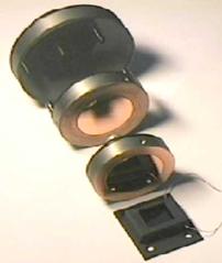 |
Fig.3. Outside appearance of BDM. From top to bottom: multichannel mirror └ę26, coolable one-channel mirror └ę24, one-channel mirror └ę22, one-channel cylindrical mirror └ę27. |
 |
Fig.4 BDM design.
1-substrate, 2-piezoelement, 3- filling, 4-cap, 5- electric connector.
|
BDM consists of substrate 1 jointed with a piezoelement 2. Piezoelement polarized in direction that lied in the plane of the draw, therefore under control voltage coinciding in sign of field of polarization it thickness increases but diameter ¢ decreases. As the piezoelement is hardly jointed with substrate, diameter decreasing induces bending of the whole construction while surface of BMD becomes convex.
Outside substrate surface processed with optical quality and deposited reflecting and protecting coatings. Inside the body the piezoelement is protected with foaming seal, serves also as a damper.
A forced cooling can be performed through the system of channels made in the substrate.
Technical specifications of BDMs are presented in tab.1
Table 1.
Technical specifications of BDM
| ## |
Parameter |
Type of BDM |
| AT22 |
AT24 |
AT26 |
AT27 |
1 |
Substrate material
| Molybdenum |
Fused silica |
| 2 |
Quantity of the control channels |
1 |
1 |
20 |
16) |
| 3 |
Specified initial shape of reflecting surface |
Plane6) |
| 4 |
Admissible deviation of real initial shape from specified, fringes ?=0.63 micron |
1,5 |
| 5 |
Theoretical shape of reflecting surface under control voltage |
Sphere |
Parabolic cylinder |
| 6 |
Admissible deviation of reflecting surface under control voltage from theoretical shape, fringes ?=0.63 micron |
1,5 |
- |
| 7 |
Light aperture, mm |
Diameter 42 |
Diameter66 |
15x22 |
| 8 |
Maximum value of incident power, kW |
1 |
10 |
21) |
- |
| 9 |
Forced cooling, coolant |
No |
Water |
No |
No |
| 10 |
Coolant pressure, bar |
- |
2 |
- |
- |
| 11 |
Coolant flow rate, L/min |
- |
0,25 |
- |
- |
| 12 |
Maximum frequency, Hz |
>50 |
| 13 |
Sensitivity, micron/kV |
45 |
42 |
3002), 303), 104), 35) |
40 |
| 14 |
Range of control voltages, V |
-200...+300 |
-500...+600 |
-200...+300 |
| 15 |
Range of curvatures, 1/m |
+1/15...-1/22 |
+1/16...-1/25 |
- |
- |
| 16 |
Hysteresis, %, no more |
20 |
| 17 |
Capacitance, nF, no more |
180 |
280 |
120 ±¾ņņÓĒÓ |
20 |
| 18 |
Wavelength, micron |
10,6 |
10,6 |
1,06 |
0,8 |
| 19 |
Reflecting coating |
Cu |
Multilayer dielectric |
Au, Cr |
| 20 |
Protecting coating |
Rare eaths oxids |
- |
- |
| 21 |
Life expectancy, cycles |
- |
- |
- |
- |
| 22 |
Overall dimensions, mm |
Diam.60§137) |
Diam.70§147) |
Diam.91§52 |
43§50§10 |
| 23 |
Weight, kg |
0,25 |
0,32 |
0,45 |
0.05 |
Notes:
1. Laser induced damage threshold, J/cm2 under impulse duration 3 ns
2. In control channel #0
3. In channel #1
4. In channels ## 2..7.
5. In channels ##8..20.
6. Others on the customer demands.
7. Without electrical connector.
Some comments to the table are to be done.
- Material
Deformable mirrors may be divided into two classes concerning the properties of the substrate: metal and dielectric. As a rule, metal mirrors intended mainly for technological č╬2 lasers, dielectric ¢ for others.
Table 2.
Materials,
used to produce deformable mirrors.
| Title |
Sort, mark |
Density, t/m3 |
Young's modulus GPa |
Shear modulus, GPa |
Poisson's ratio |
Coefficient of termal expansion, 10-6 |
Brinell harness number, MPa |
Thermal conductivity, W/ņ.╩ |
| Molybdenum |
╠ū┬Ž |
10,2 |
310 |
120 |
0,31 |
5,27 |
1800 |
138 |
| Stainless steel |
12š18═9ę |
8 |
200 |
- |
- |
16,6 |
1350-2000 |
14,5-15,1 |
| Steel |
š┬├ |
8 |
200 |
- |
- |
11 |
- |
- |
| Invar |
32═╩─ |
8 |
- |
- |
- |
0,9 |
- |
11 |
| Copper |
- |
8,96 |
110-130 |
41,5-44 |
0,38 |
16,7 |
400-1000 |
400 |
| Aluminium |
- |
2,69 |
70 |
25-26,5 |
0,31 |
23,3 |
150 |
237 |
| Silicon |
- |
2-2,33 |
110-160 |
- |
- |
2,54 |
- |
150 |
| Glass ceramic |
č╬115╠ |
2,5 |
110-160 |
- |
- |
0,25-0,6 |
- |
1,2 |
| Fuzed silica |
╩┬ |
2,2 |
74 |
32 |
0,18 |
0,4 |
- |
1,2 |
| Piezoceramics |
ųęč-19 |
- |
73,4 |
26,8 |
- |
4-4,5 |
- |
- |
| Sapphire |
- |
4 |
382 |
- |
- |
6,7 |
- |
47 |
| Glass |
╦╩-7 |
2,3 |
69,3 |
29,1 |
0,19 |
4 |
- |
1,2 |
| Silicon carbide |
- |
3,22 |
392 |
- |
- |
2,8-3,3 |
- |
350 |
| Silver |
- |
10,5 |
72-83,5 |
27-29,5 |
0,37 |
19 |
- |
430 |
We manufacture our metal mirrors from Molybdenum, considering it high hardness, strength and thermal conductivity.
As for as fuzed silicais concerned that is material widely used in optical purposes, so it use in deformable mirror seems not need comments.
Of course the table do not to be cosidered as completed nor material diversity nor items have covered. For example material polishing ability, corrosion resistence and similar technology properties do not presented.
- Control channels quantity One-channel and multicnannel mirrors differ principally. Up-to-date segmentation techniques make possible practically any segmentation layout. Conventional accuracy of linear dimensions of segmentation layout equals ?0.2 mm and minimal segment size jf about 4-5 mm.(We do not consider here inherent to seniconductor industry techniques of photomasking.) Obviously, there is problem to control multychannel mirror with number of channels more 103, but the problem can be solved.
Fig. 4 shows two different segmentation layouts for 19 channels of control.

Fig. 5. Examples of layouts for segmentation of multichannel BDM.
- Specified initial shape of reflecting surface The plane is simplest techology achiveable shape. Sometimess spherically concave shape is preferable.
- Admissible deviation of real initial shape from specified. If specified plane surface shape this parameter is equivalent to PV-PWR.
Fig. 6 shows initial shape of metal mirror.
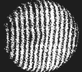
Fig. 6. Typical initial shape interferogram of the mirror AT24.
- Theoretical shape of reflecting surface under control voltage It is very important, that BDM has theoretically spherical working shape. For the illustration in table 2 are given Zernice coefficients for empirical interference picture of the mirror AT24.
Table 3.
Zernike polynomials expansion coefficients, (fringes , lambda=0.63 micron) of the experimental response function of the mirror AT24 under control voltage 20 V.
| Term number |
Value |
Term number |
Value |
Term number |
Value |
| 1 |
0 |
8
| 0.039 |
15
| 0.018 |
| 2 |
0 |
9
| -0.007 |
16
| -0.025 |
| 3 |
0 |
10
| -0.064 |
17
| -0.031 |
| 4 |
1.260 |
11
| -0.024 |
18
| -0.036 |
| 5 |
-0.014 |
12
| 0.039 |
19
| 0.002 |
| 6 |
0.001 |
13
| -0.015 |
20
| 0.026 |
| 7 |
-0.065 |
14
| -0.030 |
21
| 0.013 |
From the data of table 3 one may see that response function generally corresponds to defocus member Z4, which exceed the rest at last by an order of magnitude.
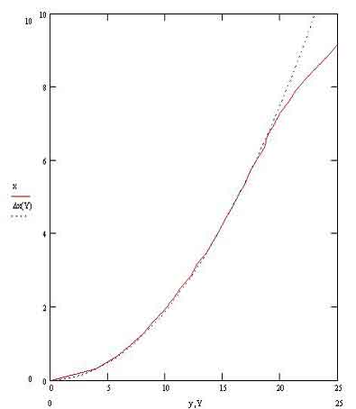
- Admissible deviation of reflecting surface under control voltage from theoretical shape Under special conditions deviations from theoretical shape may be observed.
 |
| Fig. 7. Shape deviation of BDM from theoretical (microns). Left ¢ on the periphery, right ¢ in central zone.Solid curve ¢ experiment, dots ¢ theory. abscissa ¢ radial coordinate in mm. |
Shape departure of BDM from theoretical on the edge related with changing of fastening conditions, in central zone rather with non-uniformity of the piezomaterial. It si nesesary to point out that all deviations are small enough (less then lambda/20, lambda=10.6 micron).
- Light aperture It seems insufficient for some applications. There are technology possibility to produce mirrors up to 500 mm in size.
- Maximum value of incident power. (Laser beam damage threshold) It value is confirmed with testing.
- Forced cooling inherent only to AT24 mirror. Coolant (water, for example) are to be free from particles, as cooling channels have small cross section (less 0.5x0.5 mm).ĶņÕÕ“ “Ņļ³ĻŅ ńÕĻÓļŅ └ę24.
- Maximal frequency.Really first resonant frequency equals several kHz (see fig.8). -
Filling of the mirror with a coolant reduces Q-factor in 2-3 times and resonant frequency approximately on 10%
Fig 8. Amplitude (microns) versus frequency response characteristics of BDM AT24. On the left ¢before, on the right after filling with foam seal.
- Sensitivityis determined from a sag dependence from control voltage. Sag must be measured over optical aperture. Sensitivity is proportional to piezomodulus d31. The piezomodulus has maximal value just after the polarization process. Then piezomodulus reduces for several weeks down to 50% of initial and then keeps constant for longtime. Minimal values cited that inherent to the end of lifetime .
- The range of control voltages are limited from positive values by the electric breakdown voltage, from negative values the range restricted by the damage of re-polarization of the piezomaterial.
- Curvature range Cuvature means a value inversed to curvature radius value. Curvature more convinient for specifing as it has small and continious values. Cuvature radius has infinity value at plane surface.
- Hysteresis has electromechanical hysteresys ¢ i.e. the phase of deformation is lated relatively phase of applied voltage (fig. 9).It phenomenon based on dynamic elastic hysteresys complicated with ferroelectric hysteresys in piezoceramic material. The square of the hysteresys loop measures the value of internal friction and characterizes thermal losses..
.
Fig. 9. Dependence of the center displacement of BDM in fringes (W) vs. applied voltage (U)
As an example a dependence of the temperature of separated BDM AT24 versus operating time under different frequencies shows on fig 10. (Pay attention, it is test, but not working regime.)
Fig. 10. Dependence of the temperature of separated BDM AT24 vs. operating time (minutes). 1 ¢ Rectangle control voltage at frequency 100 Hz and with amplitude from ¢170 up to +180 V. 3 ¢ The same, but at frequency 50 Hz.
- Lifetime. We have produced BDM since 1994 but up to now we had not failures due to any principal reasons. Available data shows that could be three reasons of failures of deformable mirrors.
* Reflectance reducing of the coating. This reason is mainly defined by environment (e.g. dust contains in air) but not inherent to the mirror.
* Solid integrity fault due to mechanical fatigue. Accounting small relative deformations in BDM it reason seems has negligible probability. Available experimental data have taken under values of ~6.106 cycles of full deformation and nothing failures were observed.
* Piezoceramics failure due to cover plate material diffuse and hence electrical shortdown. Specific liftimes for that reason are over 10-20 thousand hours.
If so, we suppose, lifetime of our BDM would be several thousand hours or 109 cycles of full deformation.
- The rest parameters of the BDM does not seem to be comment.
3. Usage of one¢channel BDM into a cavity of CW Laser.
Testing of one channel deformable mirrors were performed in CW CO2 lasers ōHARPOON-2000ö and ōHebrr-1Aö.
Being placed as a part of evacuated envelope initial plane form of the mirror changes by atmosphere pressure and becomes convex with radius of curvature 74ģ53 m. Under control voltage of full range the radii of curvature can be changed from convex +9m up to concave ¢29 m. We used collimating method for estimation of curvature radius. Mentioned deformations of BDM are linear and reversible
Obviously, that phenomenon is to take into consideration under maintaining BDM in evacuated optical systems, forming initial surface shape with account of atmosphere pressure.
For testing was used dc-excited č╬2-laser with fast axial flow of active mixture. The laser contains stable optical resonator with full reflecting concave mirror with ÓõĶ¾±Ņņ curvature radius of ¢30 ņ and semitransparent output mirrors with curvature radii of ¢30 ņ (for multimode generation) and ¢15 ņ ( for single mode). The resonator includes also several plane mirrors. All optical elements are forced cooled. The size of mirror apertures is 60 mm, jptical length of the resonator 6.5m. The scheme of the testing is shown at fig.11.
Fig. 11. Testing layout of BDM AT24 in the cavity of CO2 2 laser ōHARPOON-2000ö a) ¢ in static mode; b) ¢ in pulse-periodic mode. 1 ¢ optical cavity, 2 ¢ output mirror, 3 ¢ reflecting mirrors, 4 ¢ BDM, 5 ¢ output power meter, 6 ¢ voltmeter, 7- controllable supply, 8- pulse photodetector, 9- oscilloscope, 10 ¢ control unit, 11 ¢ pulse generator.
Testing was performed in static and dynamic regimes in one and multimode generation modes.
Results of static trial are illustrated with fig.12. In all tests stable and reproducible control of output power of the laser was obtained.
Dynamic testing was performed in multimode generation mode., Maximum frequency of control pulses was 400 Hz. pulse power of generation registered with photodetector on base of Ge-Au structure cooled with liquid nitrogen.In that test was obtained stable and reproducible regime of Q-modulation. A power pulse of generation contained a spike exceeding the body of the power pulse in 3-5 times. Duration of the spike was estimated as 0.2ģ0.4 mc.
Similar testing was performed in the cavity of laser ōHebbrö produced by jointed Russia-Bulgaria company. In that test output power was up to 600 W (that means more 2 kW of laser radiation power incident on the BDM).
Testing points out that BDM can be used for realization of pulse-periodic and Q-switched regimes in CW lasers.
4. Experimental results of č╬2 laser beam waist position control with BDM installed into Optical path.
The deformable mirror AT24 were tested in technological laser machine ōLFP ¢ Laserbeam cutting and welding systemö, created and modified by companies ½Nti Lasertechnik + Metallbau GmbH & Co. KG╗, ōHeld Lasertechnik GmbHö, ōWB-Laser GmbH.
Laser machine consists of č╬2-laser TRIAGON TR6000, serially produced by company ōWB-Laser GmbHö and portal system Robomatics, produced in Israel. The scheme of the general view is presented in fig13, optical scheme ¢ in fig.14
Fig. 11. The optical system of transportation of radiation and portal system of a laser technological complex " LFP - Laserbeam cutting and welding system "
The deformable mirror was installed instead of a regular mirror ╣3 (Fig. 13) under angle 45 degrees to the incident radiation.
Fig. 12. The optical scheme of transportation of radiation in a laser technological complex " LFP- Laserbeam cutting and welding system ".
The account has shown, that the feeding of controlling voltage on a deformable mirror allows to displace focal point down +9.6 mm and up -6 mm concerning an initial position.
 |
Fig. 13. Change of quality of a cut surface under the operation of a deformable mirror. |
The trials were conducted in cutting and perforating modes
In the cutting mode a significant improvement of the cut smoothness was observed (fig. 15), all other parameters of the procedure were being unchanged. In perforating mode a doubled efficiency was achieved.
5. Means of to develop and use of BDM.
Considerable volume of researches and developments of BDM and technique of their production have conducted at the date. The approbation one-channel BDM on a series of industrial laser technology complexes has shown, that the application BDM is perspective for improvement of quality of handling, heightening of productivity and extension of a circle of decided problems.
The "know-how" of BDM and the productive capacities already now allow to emit some hundreds of mirrors annually. It is imagined to us, that the developers of laser engineering should more intensively utilise in the development Adaptive Optics elements. Now, except for production of usual mirrors listed earlier, we intensively carry on development of deformable mirrors intended for solution of specific problems. For example, for this purpose the mirror AT27 with the cylindrical working shape is intended. Such mirror can be perspective at creation of pulse lasers of femto- and atto- second duration ranges [3].
References.
- http://www.laser.ru/adopt/intrctrl/ 11 Nov. 2000.
- K. Bar, B.Freisleben, C.Kozlik, R.Schmiedl. ōAdaptive optics for industrial CO2 laser systemsö. Lasers in Engineering. Vol.4, 233-242 (1995).
- E. Zeek, R. Bartels, M.M. Murnane, H.C. Kapteyn, S. Backus, G. Vdovin, ōAdaptive pulse compression for transform-limited 15-fs high energy pulse generation.ö Optics Letters, 25(8),587-591 (2000).
June 2001
Updated 5 Oct 2004